A simple DIY I²C (TWI) Testboard
If you want to operate numerous peripherals plenty of ICs deliver an interface to a BUS-system already on-chip.
Surely one could go with multiplexers or shift-registers, but a BUS is the most versatile…
I came into contact with a BUS the first time I really needed it, which was when I was working on my thesis.
There were plenty of relays that had to be switched on different boards that were connected over a back plane. Furthermore there were different voltages that had to be observed.
And that’s the point where a BUS comes in handy.
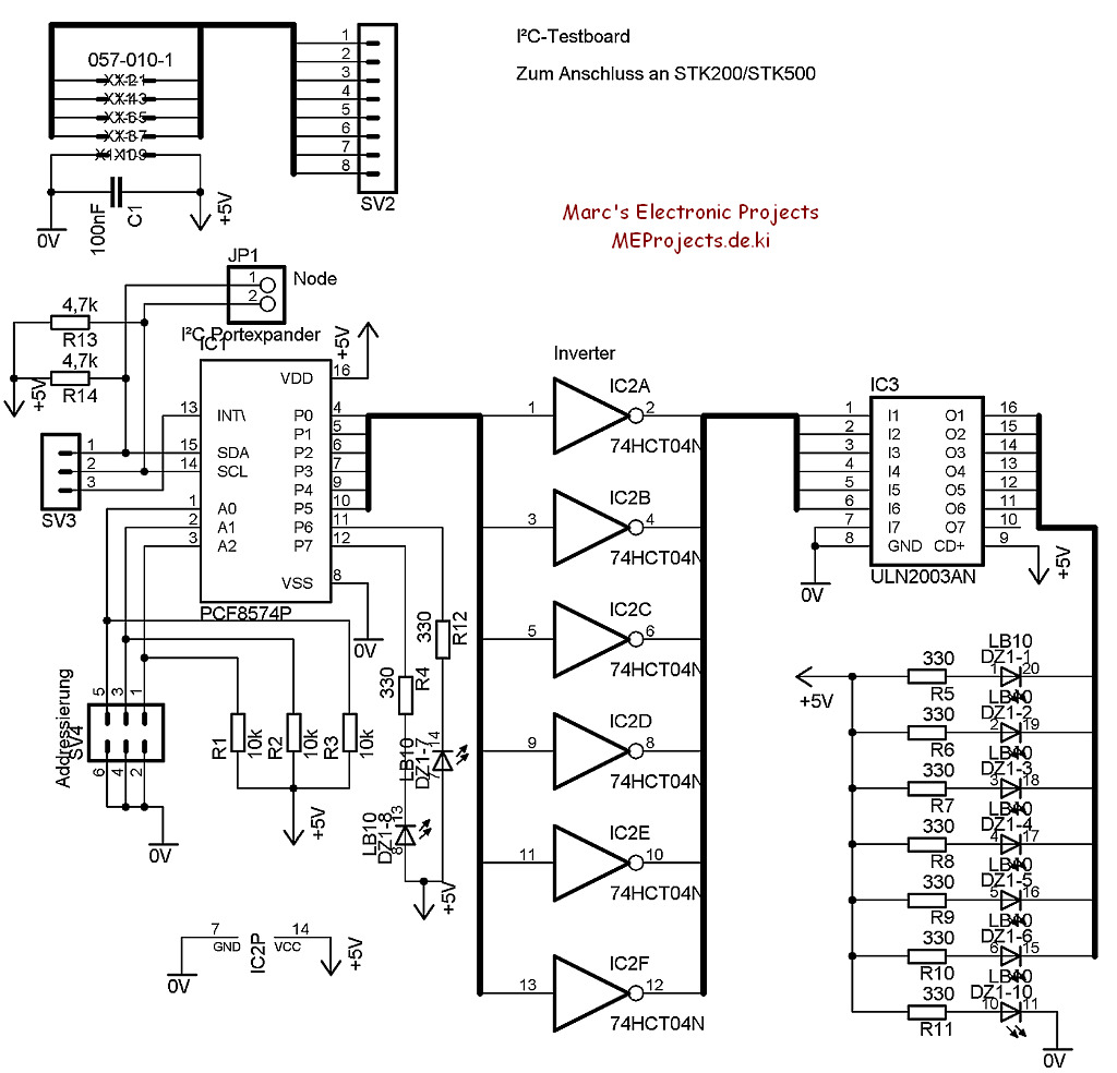
And so I developed a I²C-Testboard, which actually could simulate the switching of relays.
The I²C-IC on the board is the port expander PCF8574 which is capable of serving as an input or output to the I²C-BUS.
Unfortunately the outputs are high-level when not initialized. This is where the inverter IC 74HC(T)04 comes in.
I prefer to drive loads low-side and that is why the ULN2003 (a 7x low-side driver) is fixed to the LED-block.
The LEDs 0 to 5 (1 to 6 on the ULN2003) simulate a bunch of relays and the LEDs 6 and 7 (on the outputs of the PCF8574) are more or less just for fun.
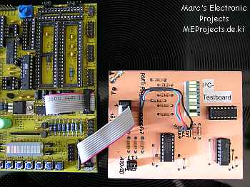
Since the digital part of my thesis is designed around an AVR-ATMega16 Microcontroller my Kanda STK200 Starter-Kit came in handy.
I could simply connect my Kanda-board with the I²C Testboard which would power it up and route the portpins from the starterkit to the I²C-board.
There I could choose by two wires (three if an I²C interrupt is required) which portpin should be used as the I²C BUS.
The three jumpers on SV4 determine the address of the PCF8574.
The BUS is only the red and the blue wire.
The black one is not used.
Here you can download a zipped .HEX file that operates the I²C BUS software-based on PORTD.2 (SCL) and PORTD.3 (SDA) on an AVR-ATTiny2313 with 4 MHz.
Additionally a LED flashes on PORTB.7 every time a I²C message is sent.
The Board is actually an etched single-sided one, but I ran out on single-sided ones, so I had to improvise a little.