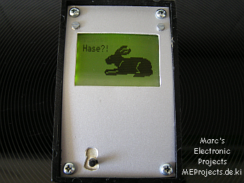
Graphics LCD based on a very cheap b/w Mobile Phones Display with SED1530 controller
At Pollin Electronic’s Website I found a very low cost graphics LCD which might come in handy occasionally.
It’s based on a SED1530 controller and it would be a nice 16×4 LCD with some graphics capabilities – so I thought.
The display is rather small (I assume it meant to be a display for mobile phones) but capable for some projects where a small display is sufficient.
Unfortunately the GLCD is not available any more at Pollin’s Webshop! 🙁
So I bought one and figured out that it runs well on the parallel interface of my PC.
But that’s really not enough for me.
I rather thought of getting it to work as a peripheral to a Microcontroller so that stand-alone applications would be possible.
The bad thing about such an idea (I found out) is that no driver is available on the entire Internet. I actually found only one driver and that was “pay-ware”.
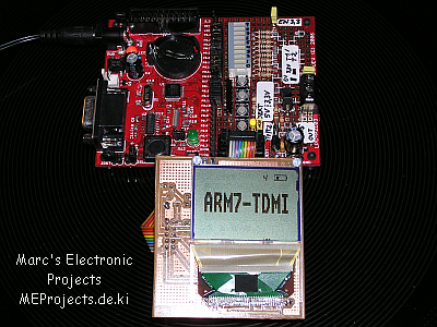
So I started to design a small PCB which could connect the LCD to my AVR Starter-Kit and programmed a driver for Atmel Microcontrollers and published it on mikrocontroller.net . Later on I ported the code to the NXP (Philips) LPC210x Microcontroller (ARM7) family.
See the .c and .h files for an overview of the driver’s capabilities.
Pleas note that the display needs a minimum of 4.5V.
So in case you are working with i.e. ARM7 microcontrollers (like in the image above) you must provide that minimum voltage.
On my LPC2103 development board I’ve got a 5V line regulator on it, fed by the power supply voltage jack.
The source-code is written in C.
You may use WinAVR resp. WINARM or any other suitable compiler under Windows or Linux.
With minor changes in the SED1530.c it should be possible to get bigger SED1530-based Displays to work, although not tested yet.
With a little help from some members from my home forum, I got the the code quite well debugged.
Please read the “notes.txt” about limitations and so on…
Code status is: 02.12.2008 A design:
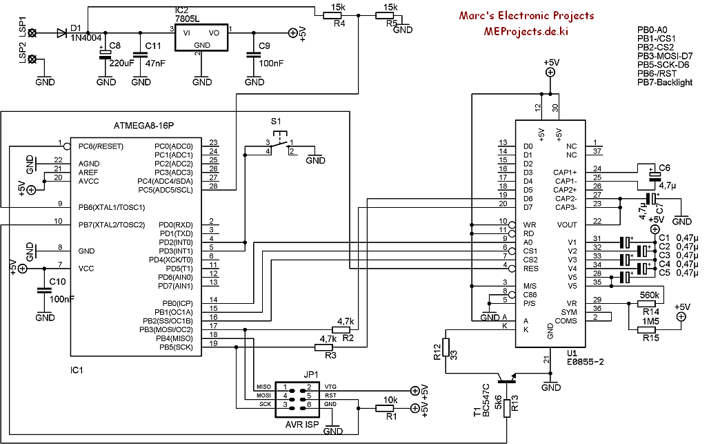
Actually designed to be a testing-platform I designed a small AVR-ATMEGA8 PCB with the GLCD on the rear.
The GLCD is driven by the hardware-SPI of the ATMEGA8.
 Hints:
If I was to design it one more time, I would apply following changes:
- CS tied up high
- /CS tied up low
- a switched power regulator (best would be a buck-boost converter i.e. MC34063 in a buck-boost configuration)
- a little flashing LED when the power is not turned off.
…
There is a lot of space in the ATMEGA8 which lets you program some gimmics such as dimming down the backlight slowly after a period of time, sleep mode for both the GLCD and the micro and periodically checking the battery voltage…