1,2A Adjustable Switching Constant Current Source with MC34063
The idea behind this little project was to design a switching and adjustable current source which keeps the load tied to the ground rail.
The purpose should be a kind of universal and adjustable current source for e.g. loading batteries or driving a bunch of standard LEDs.
Perhaps even to drive those high-power LEDs.
Furthermore it had to be a design with a large voltage range and high efficiency.
This is the point where the (nearly) “oldie but goldie” MC34063 switching regulator comes in focus.
The MC34063 is very low cost and well known.
Although this 8-pin IC can only deliver 600mA safely and up to 1.5 A peak, with a little bit of additional circuitry a stable and adjustable current source can be made.
Features:
- ca. 20mA up to ca. 1.2A, adjustable
- high efficiency, switching regulator
- very cheap
- only very few components needed
- load tied to GND
- Voltage range: ca. 6V to ca. 30V
The overall “trick” is to adjust the feedback to the MC34063 accordingly and to use an external PNP transistor, so that the high current can be delivered.
Tieing the “Load” to “Ground” is the actual little inconvenience but could be a major benefit for a next stage (controller circuit etc.).
In fact, this means that a “Sense-Resistor” has to be placed to the “High-Side” and the dropout voltage needs to be measured differentially.
By means of a suitable OP-Amp this goal can be easily achieved.
Suitable OP_Amps are i.e. LM2904, MC33172, LM358 (dual), or LM324, MC3403, LM2904 (quad) because they are designed for single supply and get quite close to the GND-rail.
Rail to rail OP-Amps should work too, but not tested.
OP-Amps which are designed for dual voltages, such as the TL072 etc. will definitely not work unless an additional negative voltage is present.
Last but not least a minimal Load should be present when the circuit is turned on. A little current flow of 1 to 2 mA is sufficient (i.e. 6.8k Resistor @ 12V – not included in schematic).
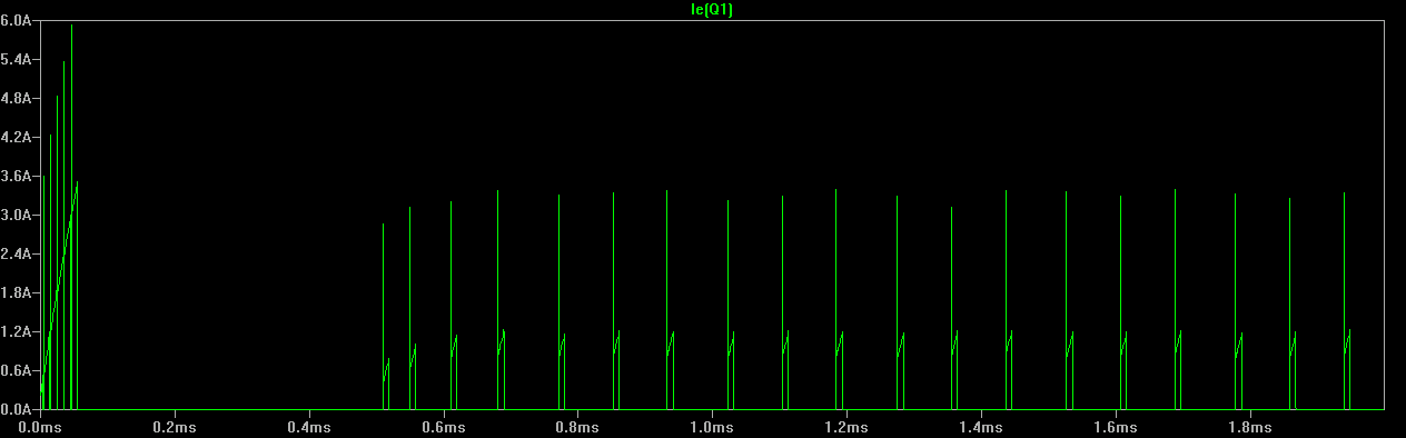
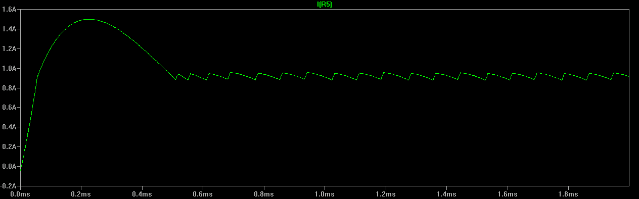
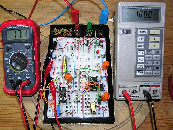
The test-circuit reacted just as simulated (load: rechargeable battery with a 200mOhm int. resistance)
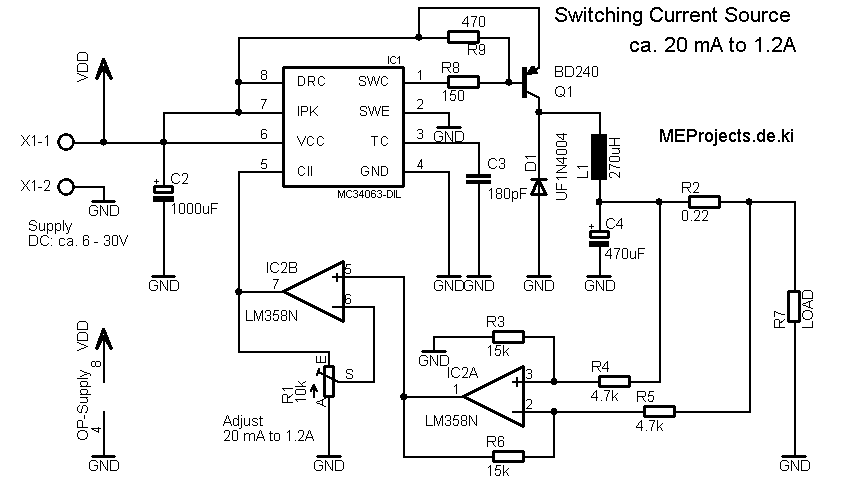
The MC34063 (IC1) is designed as a buck converter.
R2 is the “Sense-Resistor”. IC2A is the differential amplifier which amplifies the differential voltage drop across R2 and feeds IC2B, the non-inverting stage, which is used to adjust the “feedback”-voltage.
The transistor BD240 is a (2A continuous and 4A pulse current) is strong enough to deliver the current. In fact not even a heat-sink is required for operation.
A smaller type, such as the BD140 also works flawlessly.
R9 is simply installed in order to shut down Q1 a bit faster.
Vdd is simply the junction a next stage, i.e. a secondary voltage regulator for a controller circuit (or whatever).