A “Cocktail Mixing Machine”
I don’t like the shaking, mixing and all the stuff which has to be done just to get a Cocktail. I’d rather sit in a comfy chair reading a book or whatever and have a delicious cocktail made for me.
I admire those guys who are able to make a nice showing-off when throwing and flipping those bottles high in the air, catching it behind their backs while twirling around.
I once tried that too – it was really quite a mess.
Another thing is, that if you wanted a Cocktail or (even better) a little Cocktail-party, you will definitely always be reminded of that negligible tiny incident that happened eons of light-years ago when you once totally messed up the kitchen.
Since I failed doing the showing-off thing I concluded that something automated would save me from being nagged and still get my Cocktails done.
The schematic is based on an AVR-ATMega16, ATMega32 or ATMega8535.
I prefer the ATMega16 because it has enough space and has the JTAG option.
I also designed a board based on the NXP (Philips) LPC2103 Microcontroller but decided to get going with the AVR.
First of all, the concept of “Cocktail”:
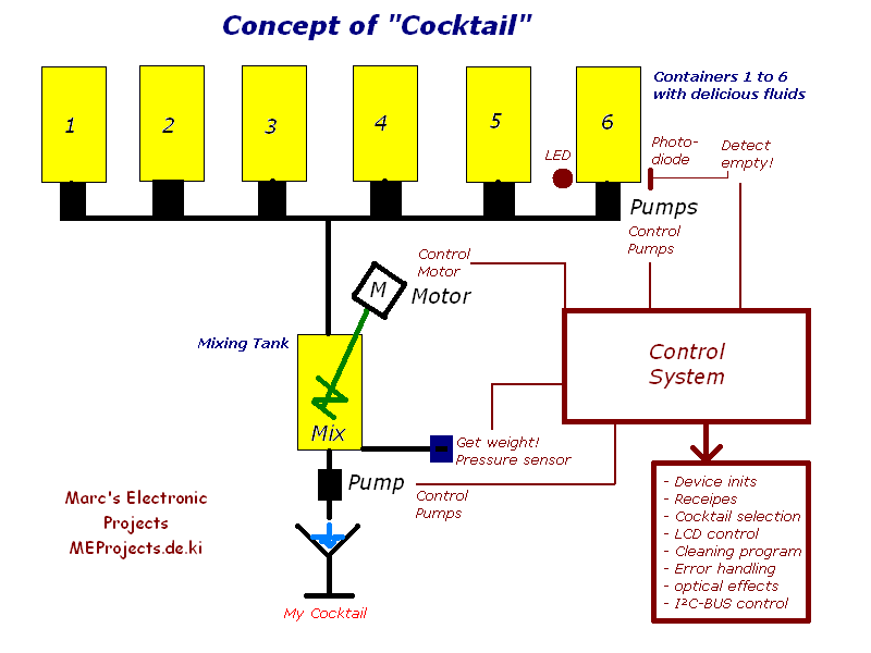
Actually, there is nothing special about the hardware concept.
There are 7 pumps and 1 motor to control (simple ON/OFF switching).
A bit more complicated are the signal inputs, specially the detection of an empty fluids-container and the determination of the correct weight which is analog to the compound’s volume.
In both cases, signal conditioning has to be done.
If you view the schematic don’t get shocked, it’s a bit bigger.
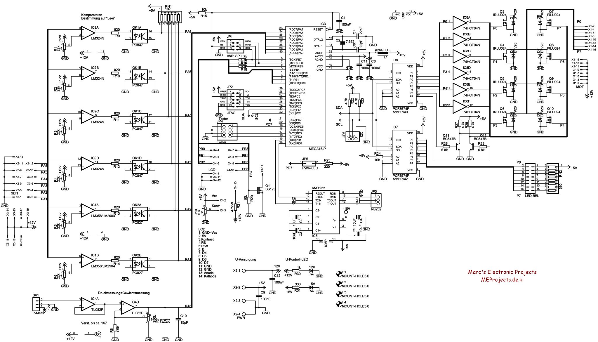
The schematic is basically divided into three parts:
The left part shows the inputs, the middle one the processing and the right one shows the outputs.
Starting from left to right let’s take a look on the inputs:
There are six OP-Amps which are connected to be comparators and biased by potentiometers.
Optocouplers pull a low-level in case a fluids container is empty, which can be detected by the Microcontroller.
I am thinking of a LED and photodiode/photoresistor combination clamped to an OP-Amp for every container.
The eighth one ist the signal conditioning for the weight sensor, also biased by a corresponding pot which delivers an analog signal to the Microcontroller.
Mid section:
The Microcontroller converts the analog signal from the eights OP-Amp into a digital one which detects low levels from the octocouplers.
Furthermore the Microcontroller is responsible for following actions:
- Initialize peripheral devices
- I²C-BUS control
- Serial RS232 (debug, bootloader, observation, I/0 and a negative voltage for an OP-Amp)
- Store all Cocktail-recipes (as an array of weights corresponding to a Cocktail-name)
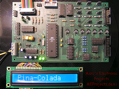
- Control the attached 16×1 character LCD (a nice big blue one)
- Cocktail selection menu (until now there are only 16 available, but I plan a Mode2)
- Error handling (what if something goes wrong )
- A cleaning program (Why should I clean a Machine if it could by itself!)
- Some weird optical effects (i.e. light-up the glass when the Cocktail is pumped into)
- Execution of the tasks needed to mix a (my) selected Cocktail
As you can see, almost everything is done in software by a 8-bit micro accept for the pick, choose and execute.
There is a ISP and a JTAG interface on the board which makes programming and debugging easy and also gives way to choosing the ATMega8535.
The right part has all outputs for controlling the seven pumps and the stirring motor.
All actuators are controlled by MOS-FET transistors.The inverter 74HC(T)04 prevents the transistors to get a high signal while the I²C BUS port-expander PCF8574 is not initialized.Unfortunately the 74HC(T)04 only has six inverters but I needed eight. So there are two small signal transistors which act as inverters.
The second PCF8574 is only for some decent light effects when the Cocktail is made…
To bad the entire control system needed to be lay-outed on a 160x100mm double sided PCB which I did not dare to manufacture myself. There were just to many through-holes and I lack the precision.
Therefore I got the PCB manufactured for me.
Not in the schematic is the power-supply.
It’s quite simple. There is an external 12V/3A notebook power-supply which will be plugged into a standard jack.
So until now the PCB is ready and the software so far programmed.
I tested everything and if works perfectly.
The next step would be to find some small pumps (suitable for edible liquids) and containers, the rest I already have.