An EZ-430 Development Board for the TI MSP430-F20xx MCUs
Thinking, that it might be interesting I bought the Texas Instruments EZ430-F2013 USB Development “Dongle”. That was long before TI came out with their low cost “MSP430 Launchpad”.
I was very intrigued by the low price and the ads said something about a whole development system including a (commercial code-size limited) C-compiler with IDE.
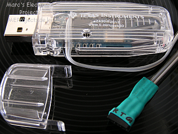
The Stick is basically a programming adapter plus a tiny detachable MSP430-F2013
chip on miniature PCB.
Furthermore the series of MSP430-F20xx micros are also available as DIP-package devices.
On the “Dongle” is only one LED which could signalize that the chip is doing something.
Although the portpins are lead out to solpads, I assumed that I’d rather damage this miniature detachable PCB than anything else.
In this rather new series of TI-Microcontrollers there is a JTAG and the new Spy-Bi-Wire debug possibility which major benefit is that it only needs 3 wires (Reset/Test/Ground).
Fiddling around with the USB-stick a figured, that as a development platform for something different than letting the “lonesome” single LED blink is actually not possible and very disappointing.
The regular F2013 board is “slightly” to small and has far to little features.
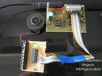
This is why I designed my own board:
The EZ430 USB stick only uses Spy-Bi-Wire, therefore this is the interface of choice.
So I detached the “tiny” MSP430-F2013 PCB and replaced it by a 1 meter, 3-wire cable.
So now the USB-stick only acts as a debugger/programmer.
EZ430_Stick
Using the USB-stick as programmer/debugger
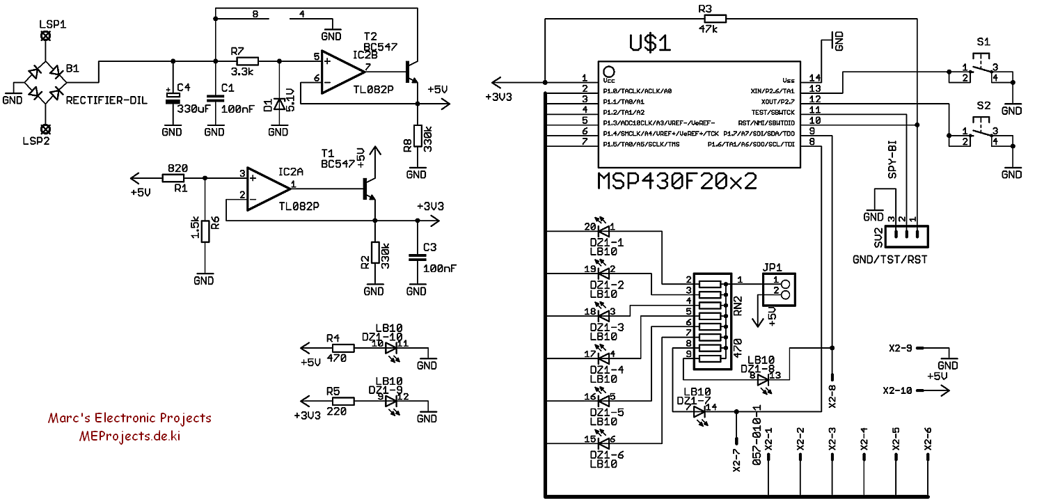
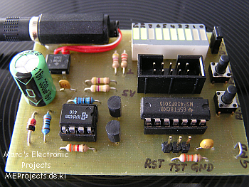
Starting with the power supply of my MPS430-F20xx Development Board I thought of a 5V and 3.3V supply, controlled a dual OP-Amp combined with two small signal transistors. That gives enough power for driving certain external TTL-based circuitry and provides the MSP430-F20xx with its 3.3V operational voltage.
The port P1 (P1.0 to P1.7) is completely routed 1:1 though a 10-pin header to LEDs.
In case something external is driven by port P1 the LEDs can be disabled by the jumper JP1.
Furthermore the 10-pin header provides 5V and GND on the last two pins.
The port P2 (P2.6 and P2.7) are connected to the switches S1 and S2 as an input feature.
The 10 LED block is driven by 5V and are low-active and the last two LEDs on the block are only showing that the 5V and the 3.3V voltages are available and stable.
Coming to terms of programming I use the free MSP-GCC toolchain and the USB-stick as a programmer and Programmer’s Notepad as the Editor of my choice.
On the net I found the free Elprotronic programmer FET-Pro430-Lite which works very well with the EZ430 USB-stick.
I did not compile the code for any other then F2013, but it should work on all other devices of that series too (tested on F2003 and F2001).