A Frequency Generator up to 100 KHz for Audio testing (Amps and stuff)
It’s generally very useful to have a Frequency Generator, since I love playing around with audio devices, specially with vintage tubes.
I started off getting a software Frequency Generator for the PC in order to produce sine and triangle wave-forms.
The bad thing about this is that the interesting bandwidth for me, what would be around 10Hz to 100KHz, ist not very well reproduced by a regular low-cost PC-soundcard.
Specially frequencies below 80Hz and above 10KHz are getting increasingly bad.
A PC-soundcard is probably quite fine for some very basic analysis but you can’t make assumptions about the signal quality of an amplifier output when the input-signal is far “beneath contempt”.
But there is hope:
For a just few bucks there are ICs available which produce good quality signals with an appropriate bandwidth and only few external components.
But, the greater the bandwidth requirements are the more expensive the ICs become.
But just only a frequency generator without a display is quite disappointing for me, so ich started off designing my own frequency generator based on the EXAR XR-2206.
According to the datasheet the IC is able to produce frequencies from 0.1 Hz up to 1MHz with triangle-, sine-, pulse-, ramp- and square waveforms.
I needed the triangle, sine and square waveforms with a bandwidth of 1Hz to 100KHz.
At first glimpse the design may seem quite complicated, but in fact is not.
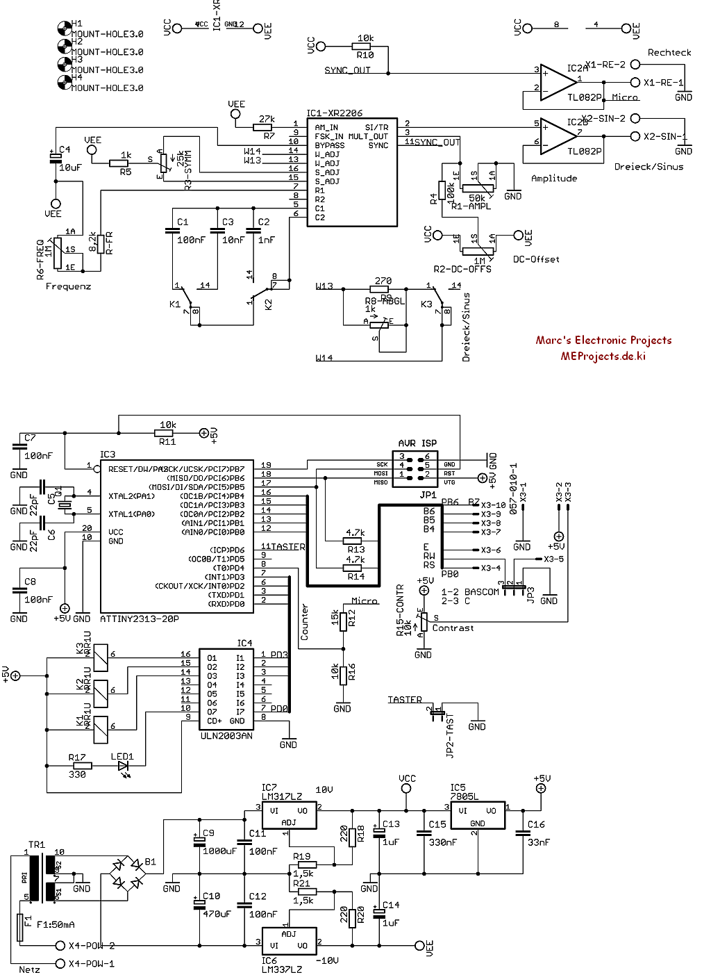
The schematic is divided into tree sections:
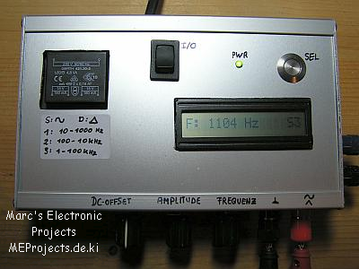
The first third is the waveform generator itself with an output buffer, the second third is the Microcontroller, which counts the frequency, manages the frequency ranges and waveforms and displays it on a 16×1 character LCD.
The last section is a symmetrical power supply, based on line regulators.
The power supply:
The power supply is symmetrical in order to provide a positive and a negative voltage for the
XR-2206 and for the output buffers.
The positive rail also provides the 5V for the micro.
The Microcontroller:
The 8-bit micro ATTiny2313 has different things to do:
- count the pulses
- evaluate a frequency
- switch the frequency range (mode)
- switch to the user-desired waveform (mode)
- display the frequency and the working mode on a 16×1 character display
That is quite a workload for the micro. A 11.059MHz crystal drives the micro fast enough, that the frequency evaluation (up to 100KHz) is quite accurate and the display-refresh is not too slow.
I used the funny frequency because this was the fastest crystal I had laying around.
The XR-2206:The determination of the frequency range is achieved by the capacitors C1, C2 and C3.
Those are switched by the micro and the relays K1 and K2.The waveforms sine and triangle are switched by K3.
As you can see, there are two outputs: One for sine and triangle, and another for square.
Since the square-output is always active (and is the count output for the micro) it has it own output.All outputs are buffered by an OP-Amp. That gives me a low impedance output and a bit more driving current. Furthermore it also acts as a security-stage. In case something weird happens it will just blow the OP-Amp. I use the TL082, a general purpose OP-Amp because it’s cheap, has a high slew rate and was just laying around.
Adjusting:
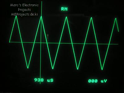
You will definitely need a scope to get the the device working.
If you operate the Frequency Generator for the first time the, be sure to select the triangle waveform and adjust the potentiometers R8 and R3 until suitable symmetrical triangles appears on you scope.